Samsung F45R6100AP Front Load Washer Service Manual with PCB and Circuit Diagram (PDF)
If you need detailed guidance for repairing or understanding your Samsung F45R6100AP Front Load Washer, this service manual has you covered. It features comprehensive instructions, PCB board details, and a clear circuit diagram to help you identify and resolve technical issues efficiently. Whether you’re a skilled technician or a DIY enthusiast, this guide offers straightforward solutions to common washing machine issues in a clear and user-friendly format.
Understanding the PCB Diagram of Samsung F45R6100AP Washing Machine
The PCB (Printed Circuit Board) diagram of the Samsung Washer gives you a clear view of how the washer’s internal electronics are connected and function together. It function like a map, showing the layout of key components, including sensors, relays, motor controls, and power supply sections.
If your washer is showing error codes, not starting, or behaving unexpectedly, understanding the PCB diagram can help you trace the problem, whether it’s a faulty component, a broken connection, or a power issue. For technicians and even experienced DIY users, this diagram serve as a key tool for diagnosing and repairing the washer without guesswork.
This model’s PCB is designed to handle multiple cycles and safety functions, so reading the diagram correctly can save time and prevent damage during repairs.
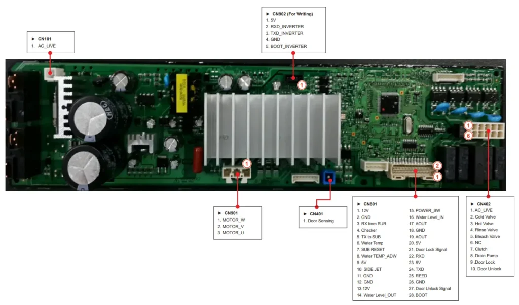
Main PCB Connection and Function Table – Samsung F45R6100AP Washing Machine
This document may not be used or reproduced without prior authorization from Samsung.
The diagram on page 32 is provided for reference only and is sourced directly from the official Samsung F45R6100AP service manual.

CN101 – PBA Power Supply:
Supplies 120V AC to the Power Board Assembly (PBA). This is the main AC_LIVE input source that powers the internal components.
RY101 – Washing Heater Relay:
Acts as a switch that controls power to the washing heater. It activates when the machine starts a heating cycle.
RY102 – Main Relay:
Delivers power to the PBA once the power button is pressed, using the AC Neutral line. It enables the main board to function.
CN901 – Motor Output:
Provides 3-phase electrical output to drive the washer’s main motor. Controls drum rotation during wash and spin cycles.
CN401 – Door Sensing:
Detects whether the washer door is properly closed. It prevents the machine from starting if the door is open or not latched.
CN801 – Sensor Connection Port:
Supplies power to various sensors and also manages signal communication between the main board and sensor units.
CN402 – Load Connection Port:
This port distributes power to various electrical components within the washer, including valves, pumps, and dispensers.
CN902 – Inverter Debugging:
Used for testing and debugging the inverter MICOM (Microcontroller) during maintenance or troubleshooting processes.
Circuit Diagram and Key Parts of Samsung F45R6100AP Main PCB Assembly
The circuit diagrams of the main components in this Washing Machine’s Main PCB Assembly show exactly how each part connects and functions. These wiring diagrams cover everything from motor control and power supply to sensors and relay circuits. They are especially useful for technicians and DIY users when diagnosing issues like power failures, sensor errors, or motor problems. Whether you’re looking to repair or better understand your washing machine, these PCB diagrams provide a clear layout for accurate troubleshooting.
Unauthorized use of this document without Samsung’s consent is not permitted.

The diagram on page 33 is provided for reference only and is sourced directly from the official Samsung F45R6100AP service manual.
Need more details? Refer to the full-service manual or wiring diagram guide for complete step-by-step schematics.
FAQs-Frequently Asked Questions
Source: Appliance Parts Pros.com
