Samsung WD106UHSA Series User Manual: Schematic Diagram Explained
The Samsung WD106UHSA User Manual is an essential resource for anyone using or repairing this washer-dryer. It provides clear, step-by-step instructions for safe operation, along with detailed troubleshooting and repair information. A key feature of this manual is the comprehensive schematic diagram, which shows how the control board, motor, heater, and sensors work together.
Whether you’re a homeowner or a technician, this manual helps you diagnose and fix issues efficiently, saving time and money by avoiding unnecessary service calls. Service Manual available below:
Samsung WD106UHSA Schematic Diagram Overview
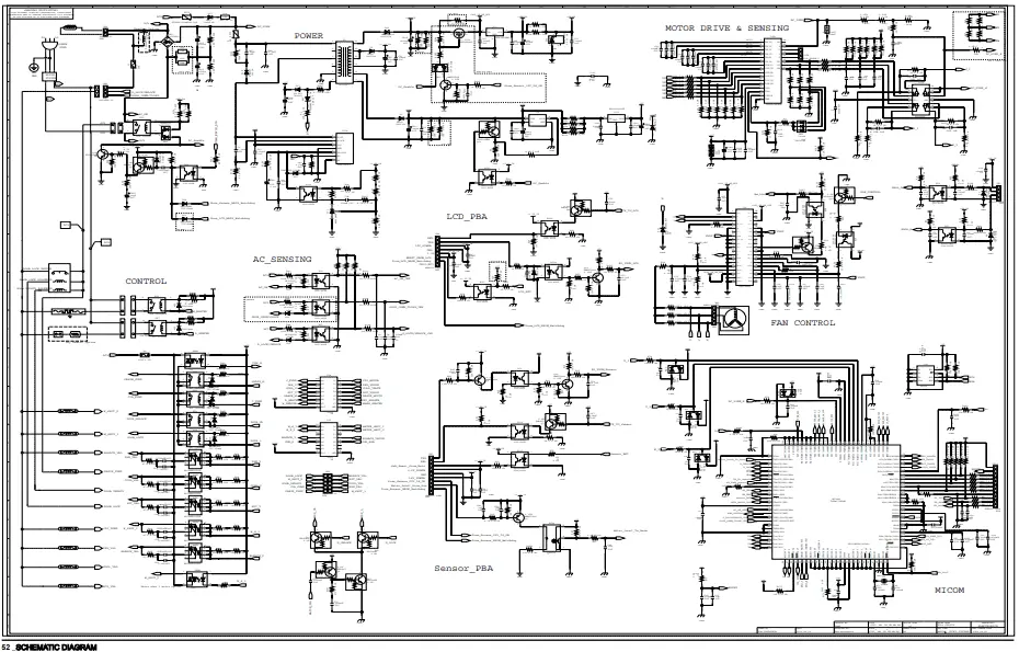
This diagram of the Samsung WD106UHSA illustrates the complete electronic circuitry of the washer-dryer’s main control system. It’s a vital reference for anyone working on diagnostics, repair, or technical writing.
MAIN CONTROL

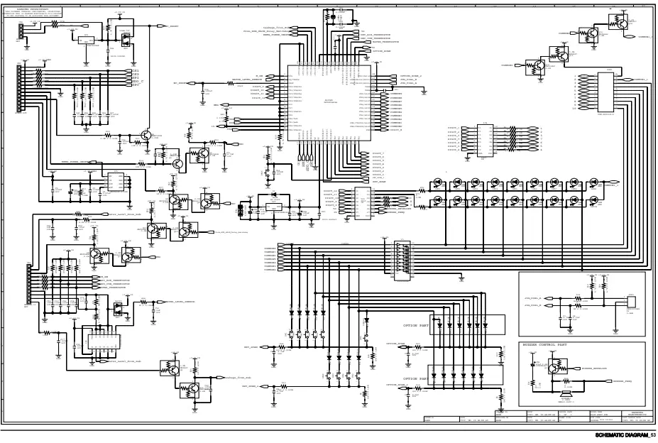
These diagrams are for reference only and have been taken directly from the official Samsung WD106UHSA service manual. For full instructions, click the “Download Manual” button above, read carefully, and apply responsibly.
SUB CONTROL

1- Key Components in the Schematic:
The schematic includes all major circuit elements used in the appliance:
| Component | Description |
| MCU (Microcontroller Unit) | The brain of the washer; controls timing, sensing, and logic |
| Relays (RY5, RY6, RY7) | Switches for heater, dryer, and motor activation |
| Rectifier & Filter Circuit | Converts AC mains to DC voltage |
| Voltage Regulator | Steps down the voltage for the logic board |
| Hall Sensor Circuit | Provides motor rotation feedback |
| Heater & Dryer Control | Power circuits for water heating and drying |
| Motor Driver (Triac/MOSFET) | Controls motor speed and direction |
| NTC Thermistor | Measures water temperature |
| Drain Pump & Solenoid Valves | Controlled through relay drivers |
2- Power Flow Explained (As Per Schematic):
- AC Mains enters and passes through EMI filters.
- It is then converted to DC power via a rectifier circuit.
- The microcontroller receives low-voltage power and controls:
- Motor (using triac or inverter circuit)
- Heater (via relay RY6)
- Dryer (via relay RY7)
- Water level and temperature sensors
Sensor feedback (e.g., Hall sensor, thermistor) returns to the MCU for decision-making.
Control Signal Flow (Simplified):
The control signal flow in the Samsung WD106UHSA washer-dryer follows a logical sequence starting from the power supply. First, the AC power supply is regulated and converted through the voltage regulator, which then provides stable DC power to the microcontroller (MCU). The microcontroller functions as the central control unit, directing signals to the motor driver circuit and relay switches.
The motor driver manages the motor’s speed and direction, while the relays control devices like the heater and dryer. Additional components, such as the NTC thermistor, water pump, and various sensors, are activated and monitored through this same signal flow. This structure allows efficient control and monitoring of every major function of the appliance.
Why the Schematic Matters:
- Helps identify faulty components (e.g., burnt triacs or relays).
- Assists in board-level repair.
- Shows exact signal routing for diagnostics.
- Essential for reverse engineering or redesigning board functions.
Where to Find the Diagram:
You can find the full schematic in the official Samsung WD106UHSA Service Manual (Section 7). It includes:
- Main Control Board Schematic
- Sub-Board Circuits
- Component References
